Термоусадочное оборудование DIEBOLD - страница 13
Навигация

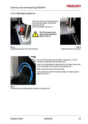
Controls and commissioning ISG3410 3.1.2.2 Mounting the guide unit Place the guide unit sub-assembly in the bores and fasten with the two enclosed screws (DIN 912 M8x30, see Fig. 5). The PE screws at the side must be fastened tightly. (Fig. 6) Fig. 5 Fig. 6 Inserting the guide unit in the machine Fastening of the PE screws On an ISG3410-WK with an option “change coil”, the lift cylinder is integrated into the linear unit. Here, the compressed air feed pipe and the return pipe have to be connected to the cylinder of the guide unit. Both connections are on the rear side. Take special care of the marked direction of rotation (Left/ Right) (see Fig. 7). Fig. 7 Connecting the compressed air hoses to the guide unit October 2015 ISG3410 13
 Термоусадочные машины DIEBOLD серии ISG 3430 TLK
 Термоусадочные машиныDIEBOLD серии ISG 3430 WK
 Термоусадочные машины DIEBOLD серии ISG 2430 TWK
 Термоусадочное оборудование DIEBOLD серии ISG 2430 WK
 Термоусадочное оборудование DIEBOLD серии ISG 2430 TLK