Термоусадочное оборудование DIEBOLD - страница 14
Навигация

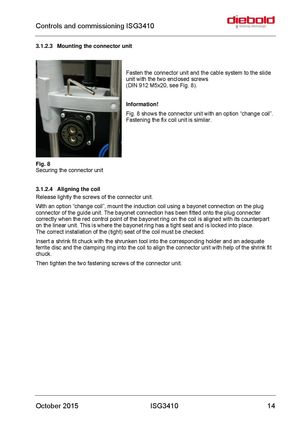
Controls and commissioning ISG3410 3.1.2.3 Mounting the connector unit Fasten the connector unit and the cable system to the slide unit with the two enclosed screws (DIN 912 M5x20, see Fig. 8). Information! Fig. 8 shows the connector unit with an option “change coil”. Fastening the fix coil unit is similar. Fig. 8 Securing the connector unit 3.1.2.4 Aligning the coil Release lightly the screws of the connector unit. With an option “change coil”, mount the induction coil using a bayonet connection on the plug connector of the guide unit. The bayonet connection has been fitted onto the plug connecter correctly when the red control point of the bayonet ring on the coil is aligned with its counterpart on the linear unit. This is where the bayonet ring has a tight seat and is locked into place. The correct installation of the (tight) seat of the coil must be checked. Insert a shrink fit chuck with the shrunken tool into the corresponding holder and an adequate ferrite disc and the clamping ring into the coil to align the connector unit with help of the shrink fit chuck. Then tighten the two fastening screws of the connector unit. October 2015 ISG3410 14
 Термоусадочные машины DIEBOLD серии ISG 3430 TLK
 Термоусадочные машиныDIEBOLD серии ISG 3430 WK
 Термоусадочные машины DIEBOLD серии ISG 2430 TWK
 Термоусадочное оборудование DIEBOLD серии ISG 2430 WK
 Термоусадочное оборудование DIEBOLD серии ISG 2430 TLK